It all started when I wanted to put up an antenna, but it couldn’t be visible from the street. The peak of my roof is 24 feet so that created the upper boundary for the antenna. That pretty much ruled out any type of horizontal antenna. The orientation of the property also ruled out any traditional antenna for the lower bands, especially 160 meters or 80 meters.
Knowing that I needed to find a solution that was as efficient as possible, I stayed with those configurations that would be resonant for whatever bands I chose to operate.
So, this began the adventure of The Backyard Antenna Experiment…

Looking at the DX Engineering website, I came across a vertical antenna that first caught my eye because of its height. After looking at all its specifications, I realized the COMTEK 30VA was a well-designed antenna mechanically, so I ordered it. At the time, I was already thinking about a quarter-wave vertical, and 30 meters was the lowest band that would fit height-wise into my self-imposed constraint of 24 feet.
I also ordered a Hustler 6BTV, as that antenna also fit my self-imposed height limit. Because the COMTEK 30VA was going to be the foundation for all my antenna experimenting, it got the more favorable location in the backyard. That meant the Hustler 6BTV got second place. Even with that said, the 6BTV has performed very well (with 20 buried ground radials). I was able to work Antarctica on 80 meters! And that was at the bottom of the sunspot cycle too. (FT-8 was a big help!)
The COMTEK 30VA was installed with 32 buried ground radials, and the testing began on 30 meters. Fast forward to now–through the various tests, modifications, and the new ideas for using the 30VA as the base for expansion to cover other HF bands.
Using cocoaNEC 2.0, I began to model how I could add various elements to the 30VA to add coverage to other bands. I did not want to do anything that would impact the already great performance of the 30VA (like adding traps, vis-a-vis the 6BTV).
Since the 6BTV did not cover 17 meters or 12 meters (in its base configuration), I decided to start with those bands as the next step of evolution for the 30VA. Because the 30VA was a full quarter-wave vertical, I thought about adding a parallel quarter-wave vertical element each for 17 meters and 12 meters. The three could be physically connected together at the base and use the existing feed line for the 30VA. The NEC models showed this would work, and the far-field patterns showed very little interaction from the elements.

Then it was back to the DX Engineering website to see what I could find to begin the next phase of adding more bands to the 30VA base antenna. Between the DX Engineering Heavy-Duty Saddle Clamps, Resin Support Block Clamps, and Aluminum Tubing, I had what I needed to begin. I know I said only 17 meters and 12 meters, but why stop there? I designed and ordered enough material from DX Engineering so that I could build four extensions from the main vertical element of the COMTEK 30VA. The photograph above shows the base design I came up with. (The green wires are many of the 32 ground radials still partly exposed, and yes, those are rocks—the favorite landscaping choice in Arizona!)
The photo below shows an additional support for the added elements. The elements are all electrically isolated at this point through the use of the resin support block clamps. The center element is the original 30VA vertical (2 inch O.D. aluminum ) and the four added elements are 1.25 inch O.D. aluminum tubing. The antenna was first assembled with only the new 17 meter and 12 meter additions. The VSWR measurements for all three bands were very good, and, more importantly, the original 30 meter VSWR was not impacted at all. By the way, the element spacing (9 inches) was arrived at empirically, a combination of available aluminum flat bars and cocoaNEC analysis.

At every step there were a number of on-the-air tests. For those thinking ahead right now, yes, the 30VA also loads up on 10 meters as a ¾-wave vertical, but the best VSWR performance is at the very high end of the band. The next test came by adding 15 meter and 10 meter elements to the other two available positions. Those also worked well! Now I had a 30-17-15-12-10 meter vertical.
Next came the reach-out goal of how could I make this same platform work on 60 meters. (I’ve run out of available space to add another antenna in the backyard and I have a lot of ground radials already in place with this antenna.)
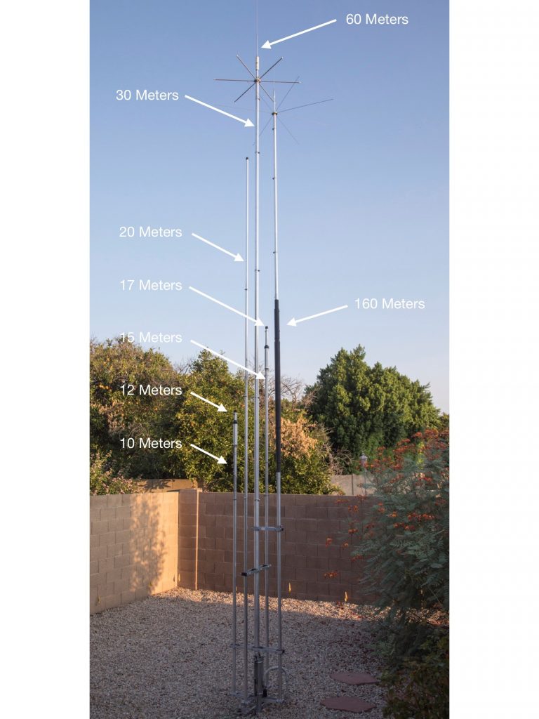
Again, fast-forward even more and this is what the antenna looks like today:
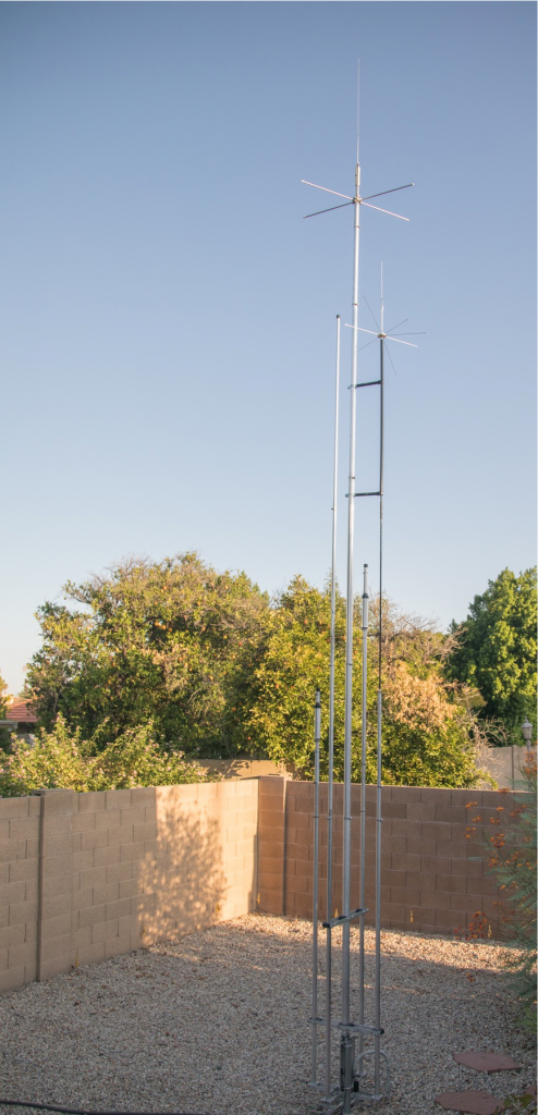
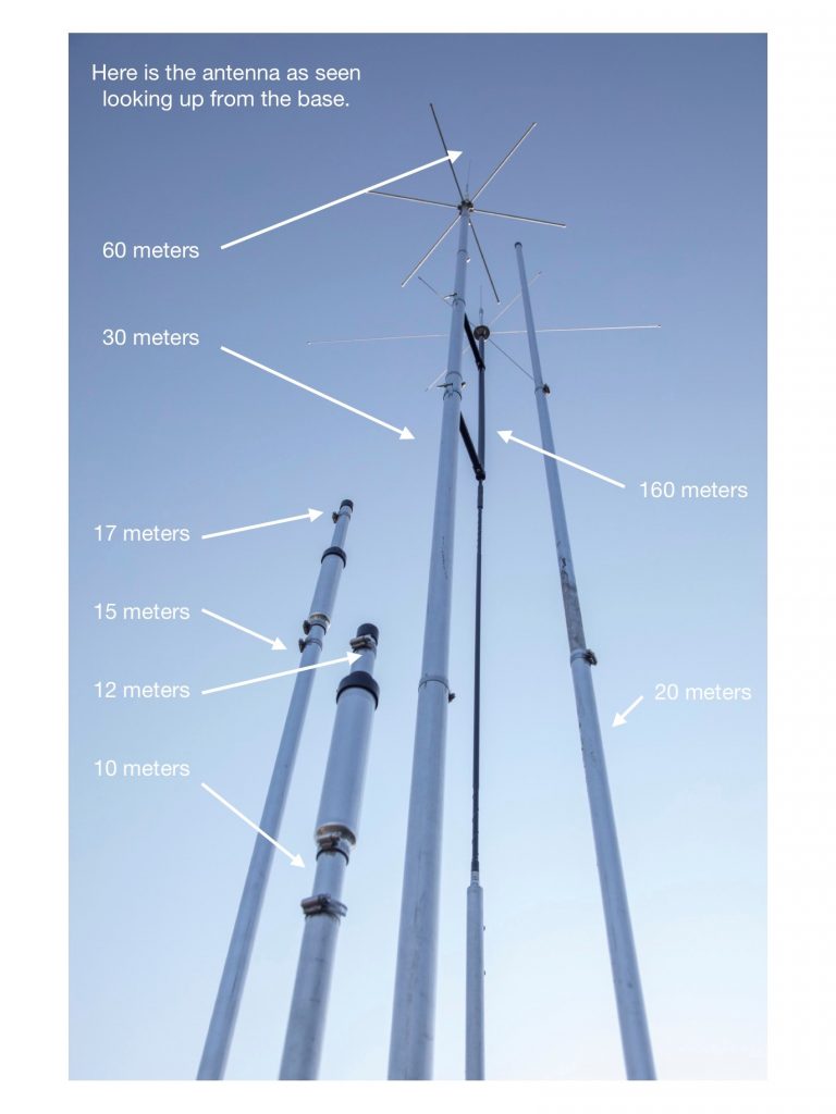
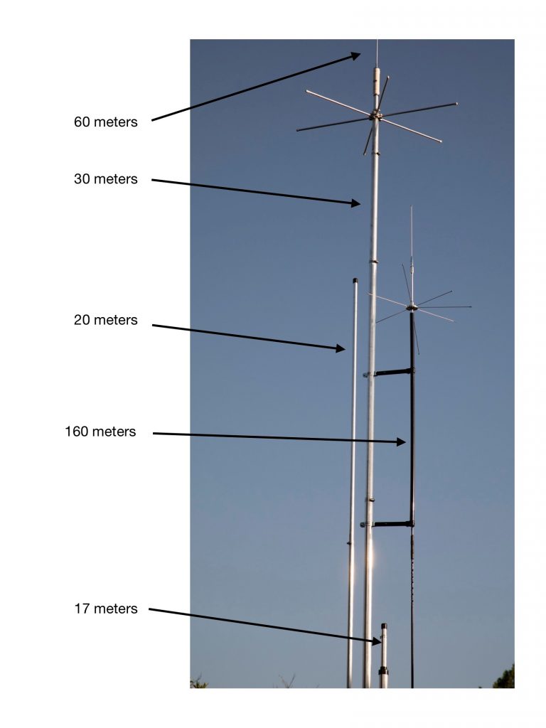
Sixty meter coverage was successfully added by first adding a capacity hat to the original 30VA so that I could reduce its height by a few feet. Then I added a Hustler RM-60 Standard Resonator to the top of the 30VA. Now there is 60-30-17-15-12-10 meter coverage.
In this long process of continual experimentation, I rearranged some of the elements along the way. Since DX Engineering provides great support for the Hustler 6BTV antenna, I was able to order a replacement Hustler BTV 10M Trap and Hustler BTV 15M Trap. This allowed me to combine a single vertical element to cover both 10 and 12 meters and a second vertical element to cover both 15 and 17 meters. Yes, I did go back on my original no-trapdesign, but for a good reason! First, that opened up space for a new band (20 meters) as its own quarter-wave element. The second space was for tackling something a little more reach out.
I’ve never been able to operate on 160 meters, always because there just wasn’t enough room for an antenna. Now, after so much success with my ongoing antenna experimental platform, I decided to try anything to see if I could add 160 meters.
So, there is one empty space for a new vertical element. I can’t violate my original constraint of no structure higher than 24 feet. After all, any antenna is better than no antenna, so what could I come up with!
By default, the design had to be some kind of loaded-vertical. So now I’m back on the DX Engineering website looking for ideas. I run across an MFJ-1675T Monoband Mobile Whip. It’s only for 80 meters so I ordered two of them and connected them back to back with a 3/8 x 24 coupler. Next I built a capacitive hat and a PVC isolation mount to support the upper part of the antenna.
Knowing this was very lossy at best, I was happy to be able to tune it and get a 3:1 VSWR for the FT-8 part of the band. Next came the big test: Could I talk to anyone? After all, it’s summer and the bottom of the sunspot cycle, so would I even get out? Using the tuner in my IC-7610 and dropping the RF power to 75 watts, I felt comfortable enough to try it on FT-8. In the first two nights of trying, I was able to make 15 contacts, with one of them being Japan. This antenna is not going to help me win any contests, but just maybe Worked All States on 160 is now a possibility.
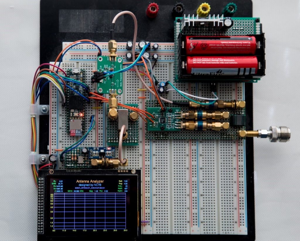
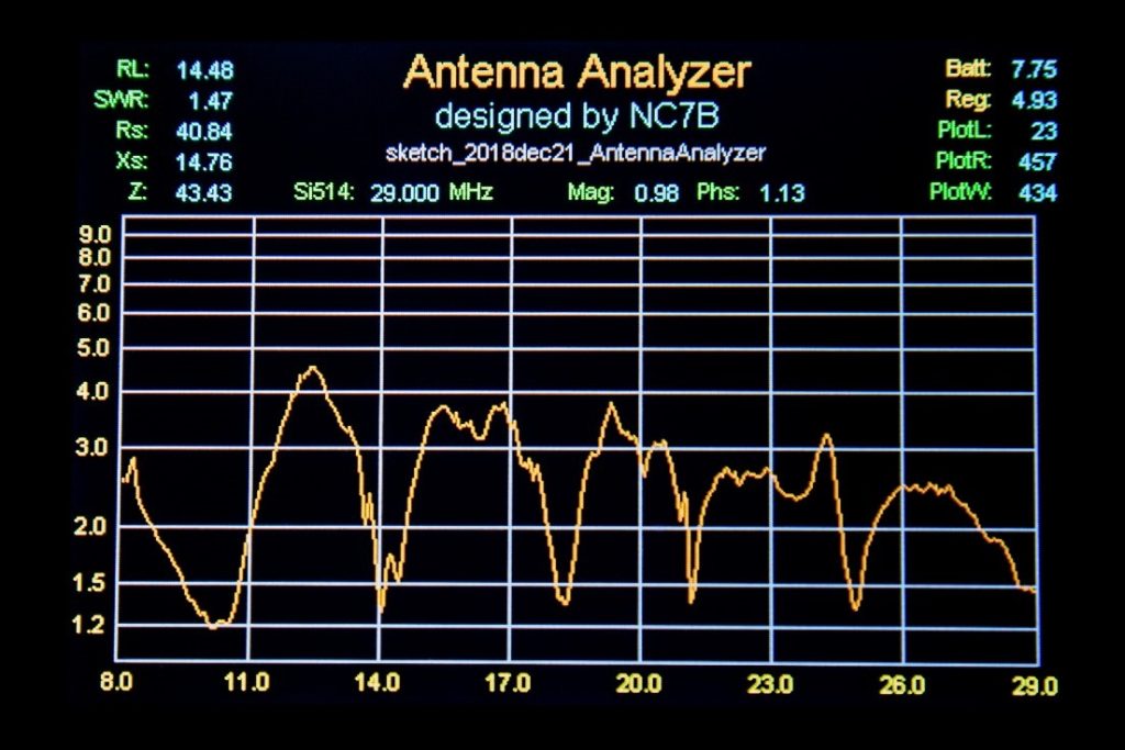
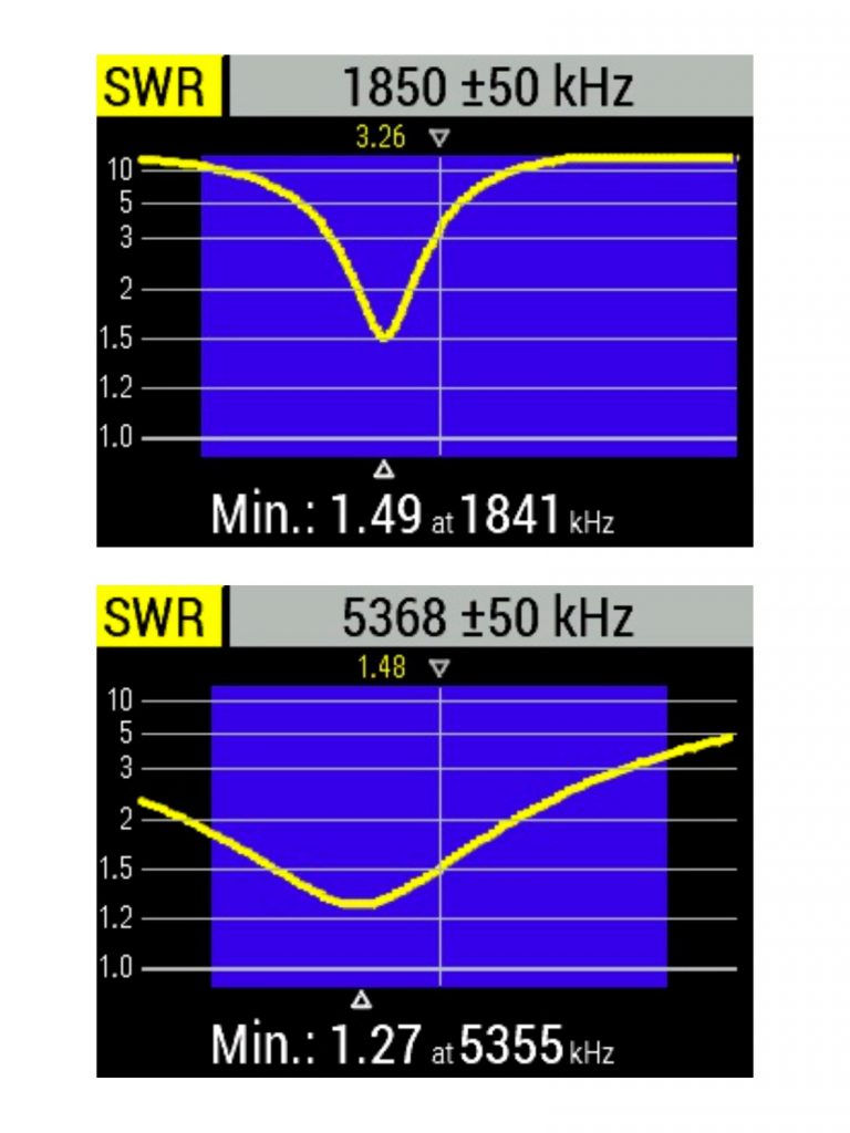
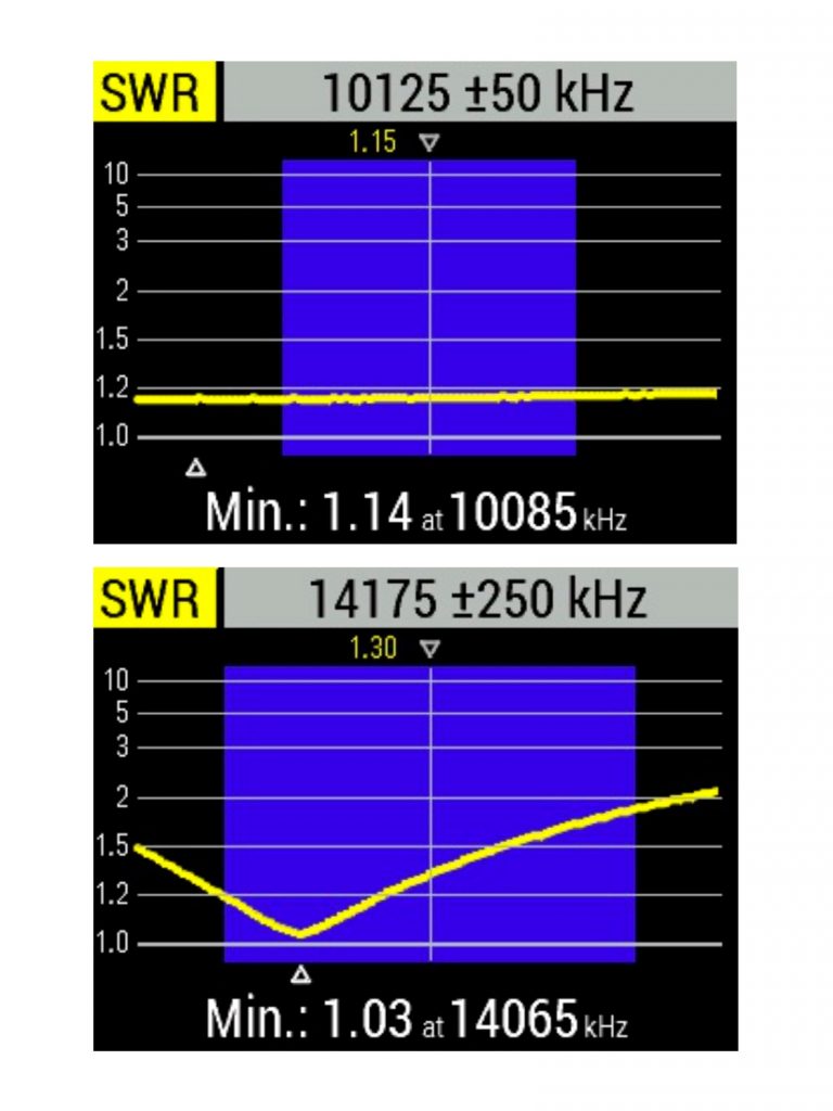
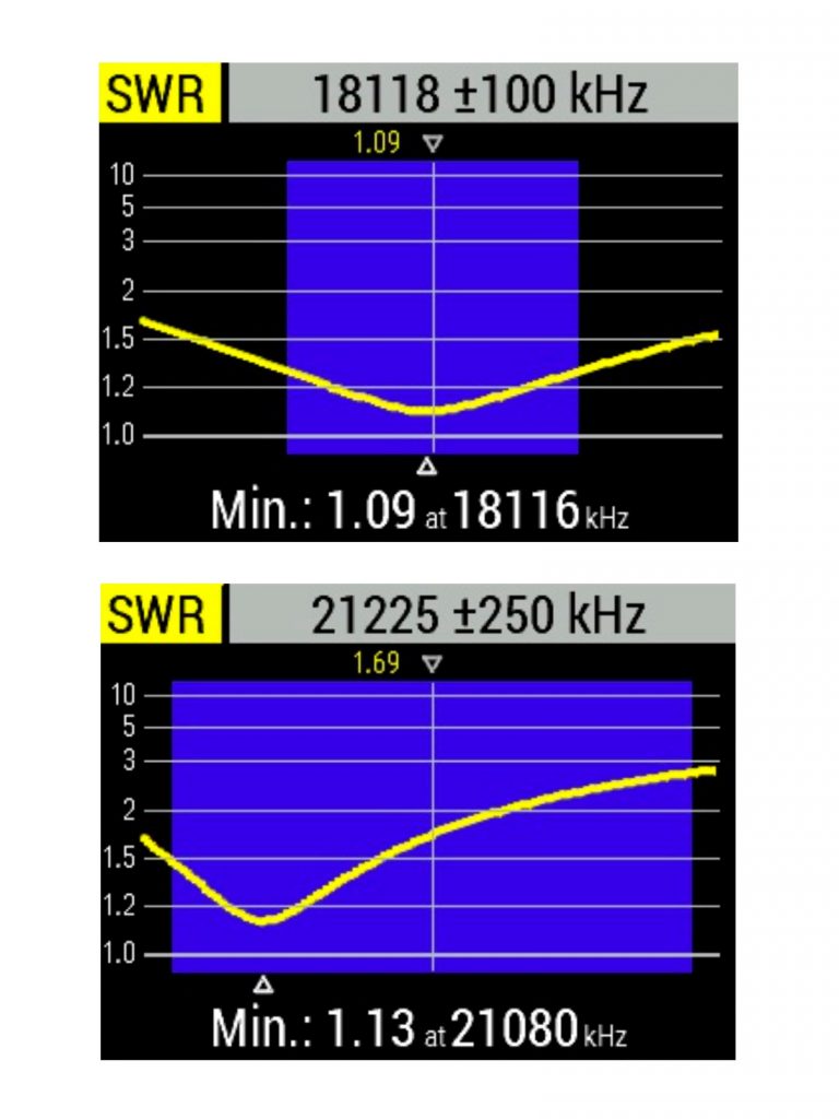
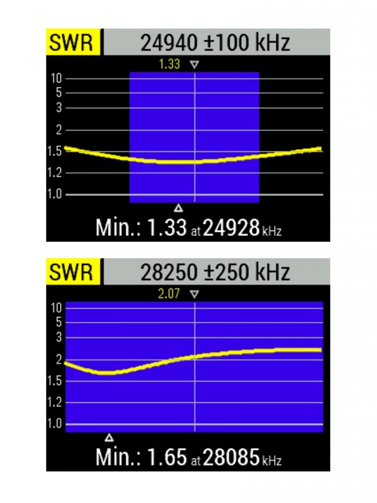
In the process of testing all the antenna configurations, I added one more project to work on. Above is the breadboard version of the antenna analyzer I designed and built for those earlier antenna tests. When I found this project wasn’t keeping up with the progress on the antenna redesigns, I resorted to purchasing a RigExpert AA-55ZOOM Antenna Analyzer. The test results below are from the RigExpert analyzer, showing the antenna performance today.


Adding a 160 meter Loading Coil
I added a 160 meter loading coil made from DX Engineering Fiberglass and Aluminum Tubing. The loading coil is 100 feet #10 wire—200 turns on 1.75″ O.D. fiberglass tube.
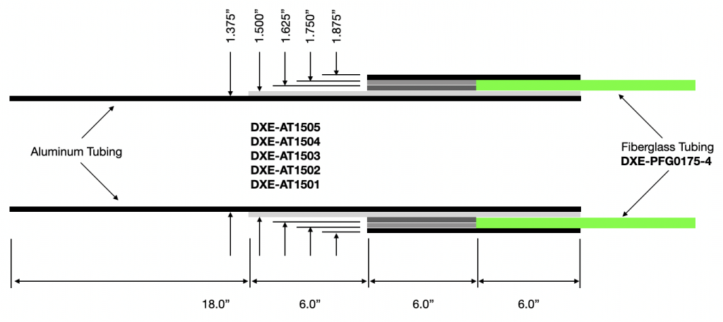
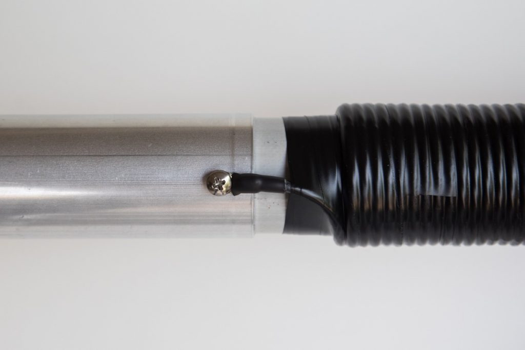
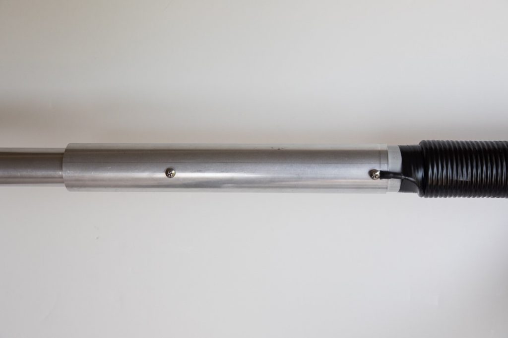
Below shows the fiberglass tube wrapped in electrical tape with additional heat shrink tubing; the loading coil installed on the antenna; and test results.

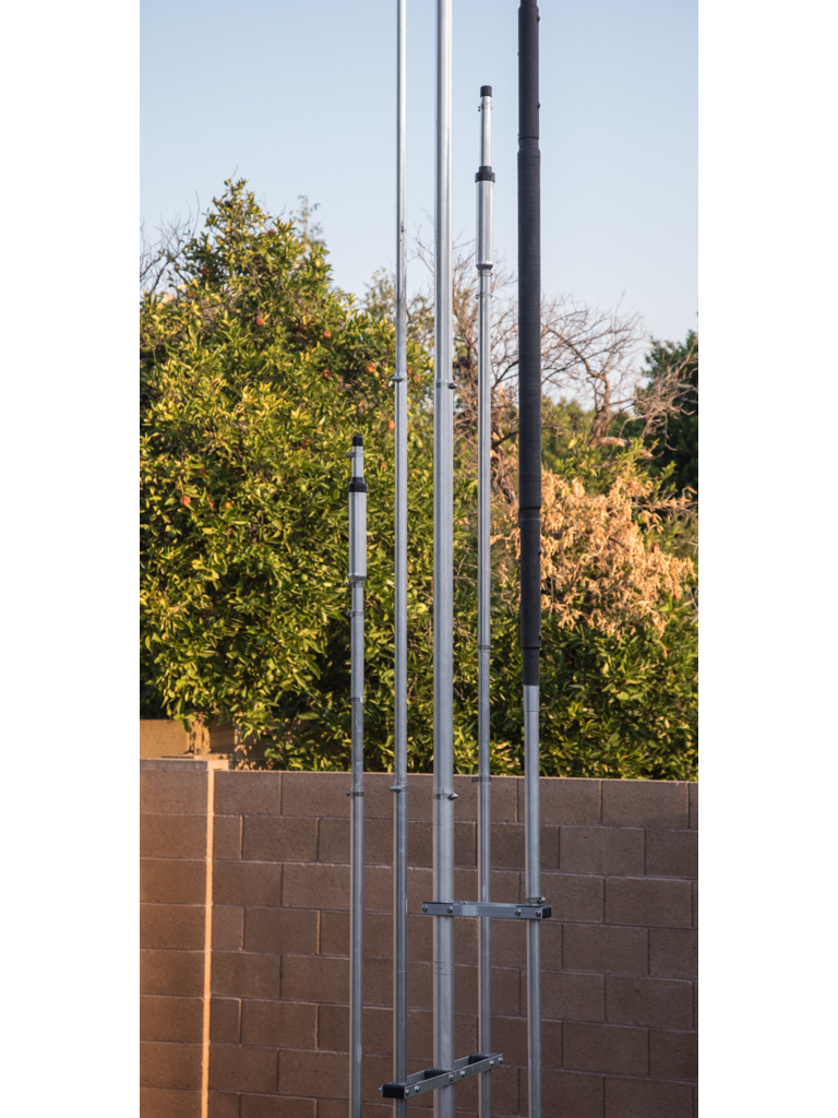
A Ham knows an antenna project is never complete, at least as long as there are more new ideas to try. The other part that makes this all possible is the vast inventory of material available from DX Engineering for all of us who want to try and build an antenna on our own.
I’m already working on my next antenna project(s), this time for 2 meters and 70cm, as I just received my new ICOM IC-9700 from DX Engineering. (That also explains the new addition of a RigExpert AA-1500ZOOM, also from DX Engineering.)

