
This is the second installment of a two-part article about RF when you are operating “in the field,” meaning away from a fixed station.
For example, when you are operating a portable station for Parks On The Air (POTA), that’s considered “in the field” whether you are in an actual field or a parking lot or not even outside. Field Day certainly qualifies in most cases. In both parts of this article, the RF from your transmitted signal is what we’re concerned with.
Mechanical Concerns
We can start with some non-RF considerations that are certainly related to antennas, but not the radiated RF.
Most antennas used in the field are either ground-mounted or lower in height than at a fixed station. This, combined with the likelihood of their being in a public space, presents a variety of hazards to passers-by and other visitors. Your goal is to keep people from walking into, tripping over, touching, or otherwise getting too close to the antennas and feed lines.
The photo below shows a typical portable station with a table, tarp, and temporary antenna about 20 feet away in the background.
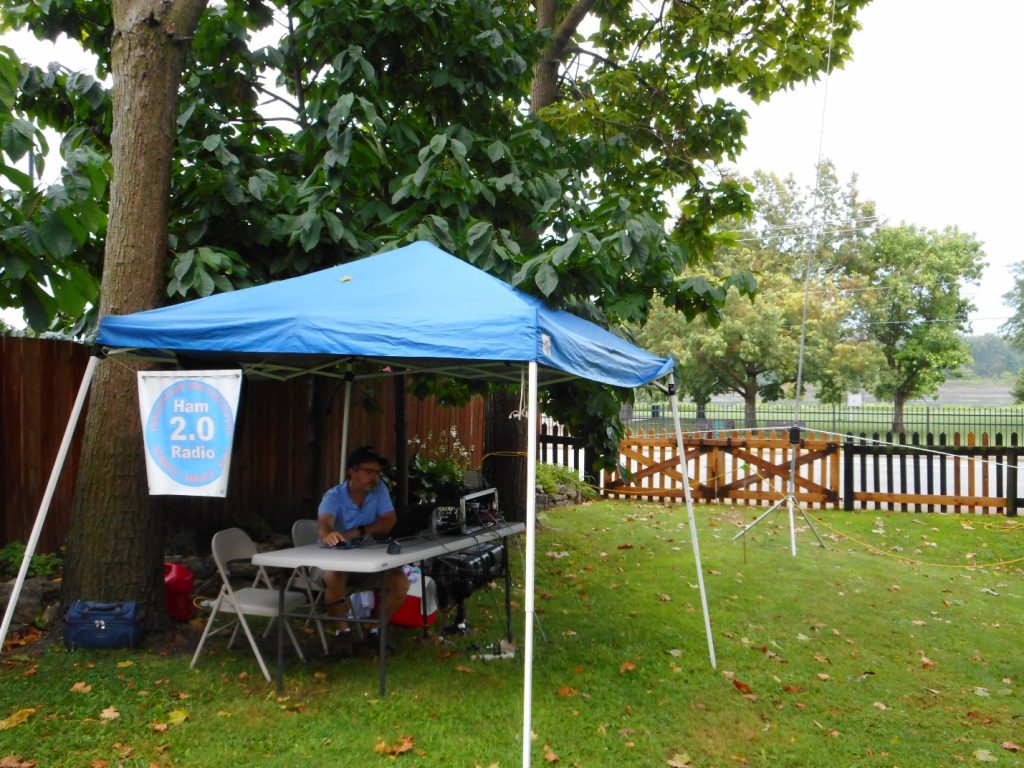
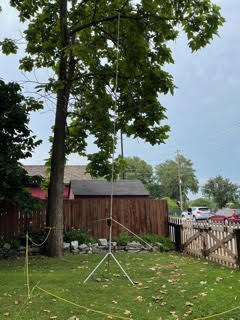
You can see the yellow rope placed around the antenna as a warning not to get too close. Plastic fence posts were used to hold the rope. Yellow caution tape is inexpensive and even more visible. Remember that many parks prohibit sticking anything in the ground, even for safety. In such cases, orange traffic cones are a good compromise.
Feed lines and power cords present a tripping hazard to both visitors and operators. If allowed, a stake in the ground next to the cables with a bit of yellow caution tape marks their location and can secure the cables. I always tie or secure the cables to a table leg so that if something does happen, the equipment is not dragged off onto the ground. (Don’t ask me how I learned to do this…)
Finally, don’t install your antenna where it can come in contact with vegetation. The end of an antenna element can present fairly high RF voltages, even at 100 watts output. This is enough to heat up leaves to the point where they will catch fire or at least smolder. Starting a fire is a definite no-no! (Don’t ask me how I learned this, either…)
Choose Your Words Carefully
Before we go any further, I need to remind you that the word “radiation” when referring to our transmitted RF may be accurate, but it is not a word the public or facility staff are comfortable with. I am careful to keep things simple and speak of “radio signals” instead of “field strength” or “radiation.” If someone asks about risks, you could truthfully tell them they might get a slight shock if they touch the antenna while you are transmitting. (If you are using an amplifier, it might be harsher than “slight,” so consider the possibilities.) Then explain that is why you have taken steps to prevent anyone from accidentally coming in contact with the antenna.
This is also a reminder to read or re-read the paragraph on preventing RF burns in the first part of this article, “RF Management—In the Field.”
RF Field Strength
The primary concern of this article is the high RF field strength near an antenna. FCC rules require us to evaluate the RF exposure from our fixed station antennas. Portable stations don’t require the same level of scrutiny, but you can use the same methods to determine whether your portable antennas might present a hazard to you or the public with respect to the Maximum Permissible Exposure (MPE).
Uncontrolled vs. Controlled
The allowed exposure levels are different for two kinds of environments—controlled (or operational) and uncontrolled (or general public). For a fixed station at our home, for example, the antennas are on private property and access to them is limited by property boundaries, fences, etc. This implies that anyone in the vicinity of the antenna either knows it is present or is there with your permission and supervision.
This is a controlled environment, and the MPE levels are higher because it is assumed the person can either take steps to stay away from the antenna or avoid being close to the antenna when the station is transmitting.
Uncontrolled environments are different and assume someone near the antenna is not aware of what it is or that it is present. They may approach the antenna at any time and are not assumed to be under your supervision, nor can they manage their own exposure.
For example, a vehicle-mounted antenna on your car in a parking lot can be approached by anyone in the lot. This is why the MPE levels are lower for uncontrolled environments. It’s safest that you assume these limits apply when considering how to construct and use your station.
High-Q Antennas
Another factor to consider is how your antenna radiates a signal and whether the RF field strength near the antenna will be particularly strong. The antenna’s ratio of stored energy to radiated energy is a measure of the antenna’s Q. Q is also known as quality factor, and for components, measures the ratio of reactance which stores energy to resistance which dissipates energy.
Antennas that store a lot of energy in the near field (within a wavelength or two of the signal frequency) can build up a surprisingly high field strength for any given power. These are known as high-Q antennas.
A high-Q antenna usually has a very low radiation resistance, which represents the antenna’s ability to radiate power into its far field, which is what launches our signals. The low radiation resistance means the antenna has to store a lot of energy for our transmitter output power to be turned into radiated signal (or heating in antenna system losses).
Imagine our antenna as a balloon being inflated by a compressor that delivers a continuous flow of air—this is our transmitter. The antenna’s radiation resistance is represented by a hole in the balloon through which air leaks out to the outside world (i.e., our transmitted signal). The balloon inflates until the amount of air leaking through hole balances the compressor’s output. The smaller the hole (the lower the radiation resistance), the higher the pressure in the balloon must be (the near field strength) for the leaking air to equal the incoming air.
The relationship between stored energy and radiated power and Q is clearly presented in a February 2013 QST article, “Q and the Energy Stored Around Antennas,” by Kai Siwiak, KE4PT. In the article, he describes and illustrates these important relationships and gives examples for real-world antennas.
For example, dipole antennas have a Q ranging from around 7 to 20, while small HF transmitting loops (a.k.a., a “magnetic” loop) can have a Q as high as 1,000. Antennas that are physically small compared to the transmitted signal wavelength generally have low radiation resistances and are high-Q.
You can tell if you have a high-Q antenna if the SWR bandwidth of the antenna is low compared to a full-size antenna. Along with the small loops, this includes popular antennas like loaded whips that are often mounted near the ground.
Tune the antenna for an SWR of 1:1 at the operating frequency. Then find the two frequencies at which SWR increases to 2.6, FU and FL. Divide the square root of FU x FL by the SWR bandwidth, FU – FL, and that will give you Q.
For example, if SWR equals 2.6 at 14.275 and 14.295 MHz, Q = 714. That’s a high-Q antenna!
Bear in mind that losses in the feed line will make SWR look a little better at the meter than it is at the antenna terminals, so the actual SWR bandwidth is smaller and Q is higher.
How Safe is Safe?
Like most questions about antenna systems, the answer always seems to begin with “It depends…” So do answers about minimum safe distances for transmitting antennas.
The answer depends on operating frequency, antenna Q, and transmitter output power. Since every portable setup is a little (or a lot) different, you can’t be modeling or making complex calculations all the time.
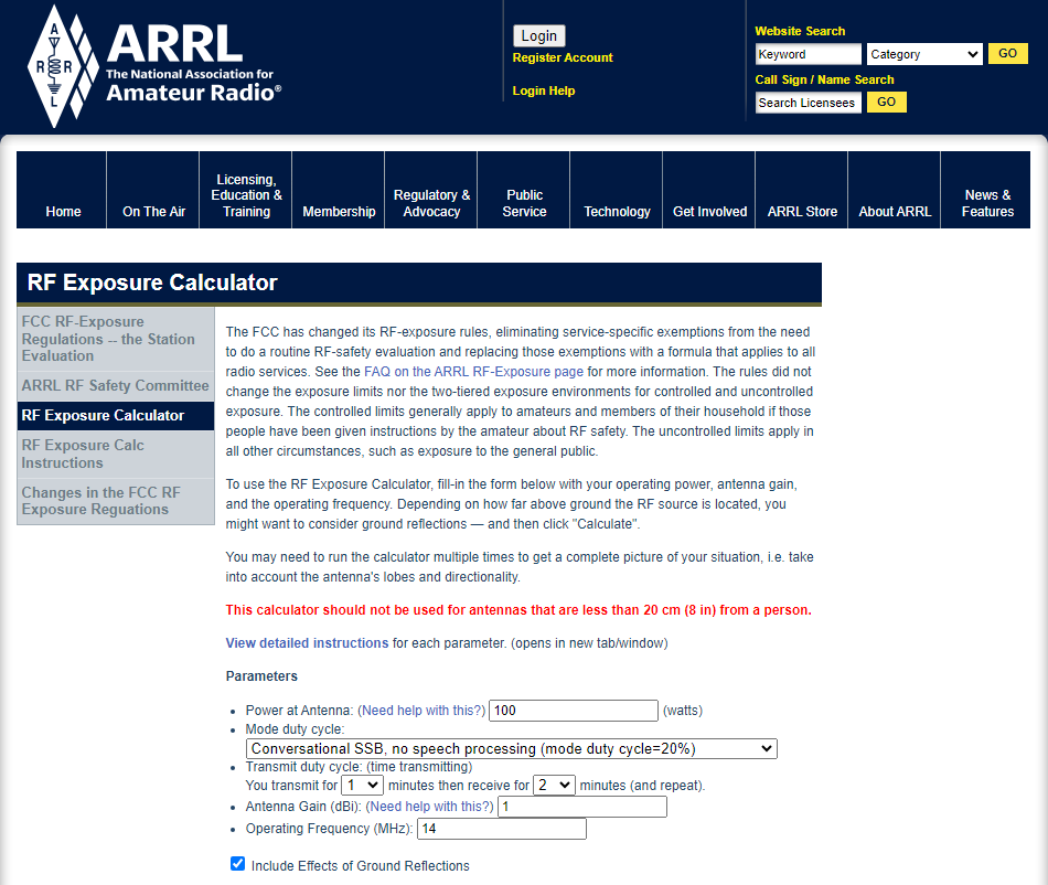
To help amateurs deal with this complexity, the ARRL provides an online RF exposure calculator.
The following is a calculation for a 100-watt, 14 MHz station using unprocessed SSB with a 20% operating duty cycle and a ground-plane antenna with 1 dBi of gain.
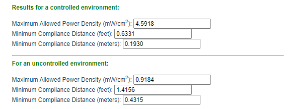
Note that it’s safe to get pretty close to the antenna. However, if I turn on speech processing or operate more aggressively, such as during a contest or POTA activation, the minimum distance will increase. Similarly, using a mode like FT8, which has a 50% duty cycle of full power on periods, will increase minimum distances still further.
This short table is an excerpt from Table 5.7 of RF Exposure and You (see this article’s conclusion for how to obtain that book) that provides typical gains for some popular portable antennas. For a vertical dipole or end-fed half-wave antenna, use the half-wavelength dipole gain. For a “hex” beam, use the two-element Yagi gain. Loaded whips are less efficient than a full-size vertical, so that antenna’s safe distances are a conservative estimate for the whip.
Typical Antenna Gains in Free Space (dBi)
- Quarter-wave ground plane – 1.0
- Half-wavelength dipole – 2.15
- 2-element Yagi – 6.0
For the special case of a small HF transmitting loop, the minimum distances are larger, due to the higher stored energy of this very high-Q antenna. Siwiak calculates these minimum safe distances in his May 2017 QST Technical Correspondence item, “RF Exposure Compliance Distances for Transmitting Loops, and Transmitting Loop Current.”
From that article, for a one-meter-diameter loop with five watts of continuous transmit power on the 40–10 meter bands, the minimum safe distance for the uncontrolled environment is 1.7 meters (5.6 feet). This increases to 2.1 meters (6.9 feet) at 10 watts output power. Table 17 from the FCC OET Bulletin 65B shows the safe uncontrolled distances for 150 watts increasing from 2.8 meters (9.2 feet) on the 40 meter band to 4.2 meters (13.8 feet) on 10 meters.
Using an amplifier, such as for a special event or contest, with a small loop increases the minimum distances on 40 through 10 meters to 17.4 feet to 42.4 feet, respectively. (A two-meter-diameter loop on 80 meters requires 21.6 feet of separation at full power.)
See Siwiak’s March 2012 QST Technical Correspondence article, “An Antenna Idea for Antenna-Restricted Communities” for more information.
Please Think About RF Safety
It’s easy to overlook these concerns in the “heat of battle” when you are just trying to get a station put together and on the air. Hopefully, this article will encourage you to consider antenna placement in the field. I see far too many pictures of portable setups where the antenna is a few feet away from a 100-watt transceiver. There are even photos of “mag loops” sitting right on a picnic table next to the operator! Don’t do that.
You can learn a lot more on the ARRL’s RF Exposure website. The excellent text reference RF Exposure and You by the ARRL’s Ed Hare, W1RFI, is downloadable at no cost as a PDF book. It has many helpful tables and examples.
I don’t think RF exposure is something we should be afraid of, but neither should we be careless in how we treat it.