(Editor’s Note: The following article is from the archives of experimenter, inventor, friend of the Ham Radio community, and founder of Clifton Laboratories, Jack Smith, K8ZOA (SK).)
In working on an active antenna and preamplifier design, I needed a broadband 1:1 transformer. I’ve wound many of these and written an article for 73 Magazine about the subject as well, but there’s always interest in broadband transformers.
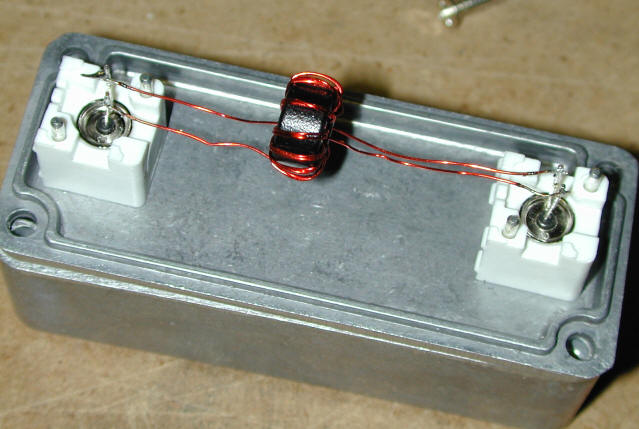
My favorite design uses a bifilar winding, consisting of two no. 26 AWG wires twisted together around 4 to 5 turns per inch, wound with 10 turns on a Steward 35T0501-H10 ferrite core.
I’ve used Fair-Rite 43 material toroid cores in the past, but where low frequency performance is necessary, I’ve found Steward’s 35 material useful. It has a relative permeability at low frequencies of 5000, compared with 800 for Fair-Rite’s 43 material, and it’s available in small quantities from DigiKey. Fair-Rite’s Type 75 material is quite similar to Steward’s 35 and may be used if desired.
One advantage of Steward is that DigiKey stocks the H10 version of the part, which is tumbled to remove sharp edges and coated with Parylene. Parylene is a smooth insulating coating which, when combined with tumbling makes it much easier to wind without scraping the enamel insulation from the magnet wire. Fair-Rite, I believe, offers a similar coating but the usual amateur radio suppliers provide only the uncoated cores.
The core used in this transformer is DigiKey stock number 240-2524-ND, priced at 23 cents each in quantities 1-9, Steward part number 35T0501-10H. The dimensions are 12.70mm O.D. x 7.14mm I.D. x 6.35mm H. It’s quite similar in size to what is known as an “FT50” to the amateur radio community, except that the Steward core is thicker (FT50 thickness is 4.90 mm). This gives you a bit more inductance per turn.
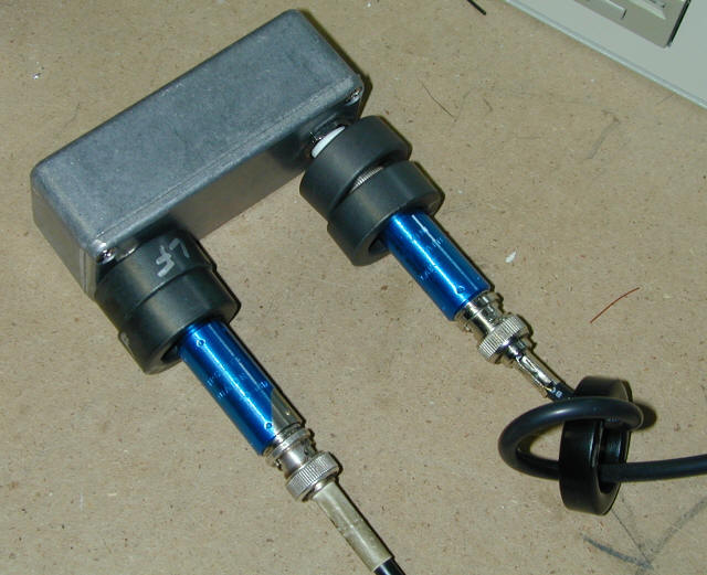
The photo below shows the completed transformer connected to two floating shell BNC connectors. The spacing between the two connectors is greater than it should be because I use the same enclosure for the Z10010 bandpass filter and happened to have a drilled cover on hand.
Although bifilar wound, I connected the windings as in a conventional transformer to provide DC and low frequency isolation, not like a balun connection that provides DC continuity between input and output ports.
The plot below shows (frequency axis is log scale) the transformer’s frequency response over the range 10 KHz to 100 MHz.
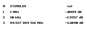
The 3 dB bandwidth extends from below 10 KHz to 85 MHz, and the mid-band insertion loss is less than 0.1 dB.
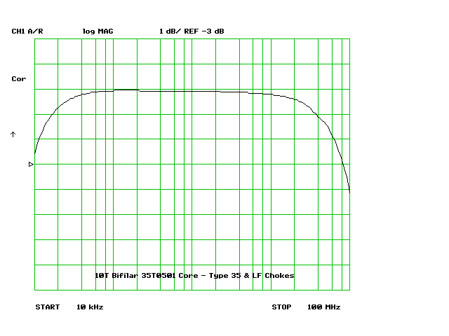
The frequency plot is taken with an HP 87510A vector network analyzer, and the first sweep I ran showed a notch around 40 MHz, as can be seen in the plot below. The depth of the notch varied as I moved the coaxial cables connecting the transformer enclosure to the 87510A and at the worst was between 2 and 3 dB.
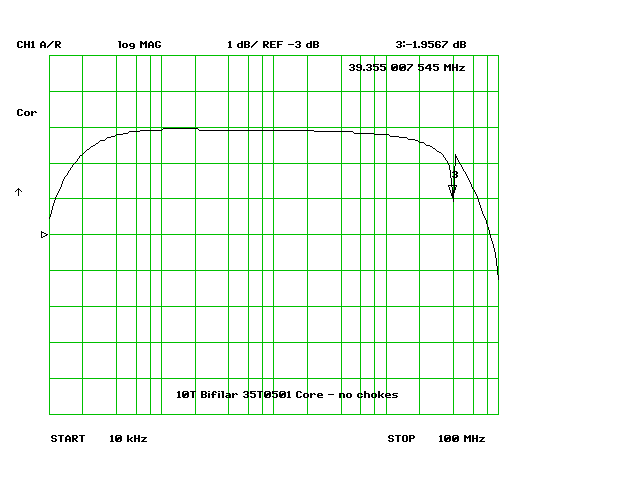
After thinking about it for a moment, it was apparent that since both side of the transformer are isolated a sneak path for RF from the VNA’s output port to the input port could exist over the coaxial cable shield. At 40 MHz, the sneak path signal interfered with the normal path. The test cables are double shielded RG-223 type, so it’s not leakage through the braid.
To test this theory, I added ferrite core chokes to both side of the transformer, two Steward type “LF” material cores and one larger Type 35 material core, as shown below, on both the input and output sides of the transformer. (The output Type 35 core is off the edge of the photograph.) The result was that the notch disappeared, with the results seen in the first frequency sweep plot.
The blue devices are Minicircuit Labs 6 dB attenuators, type CAT-6. When measuring a low loss device such as a transformer or filter, the VNA’s accuracy can be improved by adding attenuators at the input and output of the device under test, as reflections from the VNA’s source and receiver ports are reduced.
